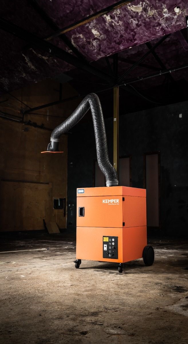
The Kemper Profimaster represents the pinnacle of welding fume extraction technology, offering superior filtration, automatic cleaning systems, and intuitive controls. However, even the most advanced equipment requires proper installation and operation to deliver its full potential. This comprehensive guide covers everything from initial setup to ongoing optimization, ensuring your Profimaster provides maximum protection for your welders and compliance with HSE regulations.
Pre-Installation Planning for Optimal Results
Before your Kemper Profimaster arrives, thorough planning can significantly impact its effectiveness and ease of use. Taking time to properly prepare will ensure you get the most from your investment from day one.
Site Assessment and Positioning
The location of your extraction unit directly affects its performance. Consider these critical factors:
Workspace Coverage: Each Profimaster arm has a practical working radius (typically 2-4 meters depending on model). Map your welding stations and ensure the planned position allows the extraction arm to reach all required welding points. For larger workspaces, multiple units or a central system with multiple arms may be more appropriate.
Air Circulation Patterns: Position the unit to work with, not against, natural air flow in your workshop. Avoid locations near doors, windows, or fans that might create cross-drafts that pull fumes away from the extraction hood. The ideal setup allows the natural thermal rise of welding fumes to aid capture.
Access Considerations: Ensure the unit has sufficient clearance for routine maintenance tasks such as emptying the dust collection drawer, checking filters, and accessing controls. Allow at least 1 meter of clearance on the service side of the unit.
Power Supply: Confirm your workshop has appropriate electrical connections for the Profimaster (typically 240V/16A for standard models, though three-phase options are available for larger units). The power supply should be dedicated and properly protected by appropriately rated circuit breakers.
Compressed Air: If your Profimaster includes automatic filter cleaning (most models do), you'll need a compressed air connection delivering 5-6 bar pressure with appropriate volume. Plan the compressed air line installation to reach the unit's connection point.
Tools and Resources Required
Prepare the following before installation begins:
- Appropriate electrical tools for connection work
- Compressed air fittings compatible with your workshop system
- Spirit level for ensuring the unit sits perfectly upright
- Tape measure and marking tools
- Basic hand tools for assembly and adjustment
- Documentation of your specific model variant
- Floor space cleared and cleaned prior to installation
Installation Process: Step-by-Step
With preparation complete, the installation process can begin. While professional installation is recommended for complex setups, many workshops successfully install their Profimaster units in-house.
Initial Placement and Assembly
- Unpacking: Remove all packaging carefully, checking for any shipping damage. Verify all components against the packing list, including the extraction arm, hood, fasteners, and documentation.
- Position the Base Unit: Place the Profimaster on a level, stable surface, using the lockable castors to secure it in position. Use a spirit level to verify the unit sits perfectly level, as this affects both filter cleaning efficiency and extraction performance.
- Arm Assembly: The extraction arm typically ships partially disassembled. Follow the specific instructions for your arm model, paying particular attention to the orientation of joints and the routing of the internal support mechanism.
- Hood Installation: Attach the extraction hood to the arm, ensuring all gaskets are properly seated to prevent leaks. If your model includes an optional LED light, verify the electrical connections are secure and properly routed.
- Arm Mounting: Connect the assembled arm to the top of the Profimaster unit, making sure all fasteners are tightened appropriately and gaskets are correctly positioned to ensure an airtight seal.
Power and Compressed Air Connections
- Electrical Connection: Have a qualified electrician connect the Profimaster to your power supply according to local electrical codes. Verify the unit is properly grounded and that the connection meets the amperage requirements for your specific model.
- Compressed Air Setup: Connect the compressed air supply to the designated inlet on the unit. Install a water separator upstream of the connection to prevent moisture from entering the cleaning system. Set the pressure regulator to the manufacturer's recommended setting (typically 5-6 bar).
- Initial Power Test: Before proceeding further, perform a brief power test to verify the unit starts correctly and all indicator lights function as expected. Do not run the unit for extended periods without completing the full setup and adjustment.
Extraction Arm Adjustment for Optimal Performance
The extraction arm's ease of use and effectiveness depend on proper joint adjustment:
- Horizontal Joints: Adjust the tension on each horizontal joint to provide sufficient resistance to maintain position without requiring excessive force to move. Begin with moderate tension and fine-tune based on actual use.
- Vertical Support: Set the vertical spring tension to counter the arm's weight, allowing it to "float" without drifting down. This typically requires adjusting the spring tensioner located near the base of the arm.
- Hood Positioning: Adjust the friction settings on the hood joint to allow easy positioning while maintaining stability during extraction. Verify the hood rotates fully through its 360° range of motion.
- Damper Setting: Set the hood damper to the fully open position initially. This can be adjusted later based on specific process requirements and airflow needs.
System Configuration and Initial Operation
With physical installation complete, the system requires proper configuration before regular use.
Control System Setup
- Operating Mode Selection: Determine whether the unit will operate in manual mode or automatic start/stop mode (if equipped). For automatic operation, adjust the sensitivity settings to match your welding processes.
- Extraction Power Setting: Configure the extraction power level based on your typical welding processes. Higher settings provide stronger extraction but increase energy consumption and noise levels. Start at the middle setting and adjust based on actual performance.
- Filter Cleaning Parameters: If adjustable on your model, set the differential pressure thresholds that trigger cleaning cycles. The factory defaults work well for most applications, but high-volume production might benefit from more frequent cleaning.
- Optional Feature Configuration: If your unit includes additional features such as operating hour meters, maintenance reminders, or network connectivity, configure these according to your maintenance program requirements.
Initial Testing and Verification
Before placing the system into regular service, conduct these essential tests:
- Extraction Test: With the system running, use a smoke tracer (commercially available or created with a smoke pen) to visualize airflow patterns and verify fume capture at typical working distances. The capture zone should extend at least 30cm from the hood in all directions.
- Filter Cleaning Cycle: Manually trigger a filter cleaning cycle and verify that the compressed air pulses function correctly. Listen for the distinctive sound of the cleaning valve operation and observe the pressure gauge fluctuations.
- Mobility Check: If your unit is mobile, verify that the castors move freely and lock securely. Ensure the power cable and compressed air line have sufficient length to allow movement within the intended work area without straining connections.
- Noise Assessment: Measure the noise level during operation to determine if hearing protection may be required for operators working near the unit for extended periods. Most Profimaster units operate at 68-72 dB(A) at 1m distance, below the threshold requiring hearing protection.
Best Practices for Daily Operation
Proper daily operation significantly affects both extraction performance and system longevity.
Optimal Extraction Hood Positioning
The single most important factor in extraction effectiveness is proper hood positioning:
- Position the hood 20-30cm from the weld, angled to capture the rising thermal plume
- For horizontal welding, place the hood above and slightly behind the weld direction
- For vertical welding, position the hood to the side and slightly above the weld
- Reposition the hood as you move along longer welds rather than working at the edge of the capture zone
- Use the hood damper to increase velocity for challenging positions or reduce it when working with shielding gas-sensitive processes
Process-Specific Adjustments
Different welding processes require slightly different approaches:
MIG/MAG Welding: Position the hood closer to the work (15-25cm) with the damper fully open to maximize capture of the higher fume volumes.
TIG Welding: Place the hood slightly further away (25-35cm) with the damper partially closed to prevent shielding gas disturbance while still capturing fumes.
Stick Welding: Use the closest practical position (15-20cm) with maximum airflow to capture the high volume of particulates generated.
Plasma Cutting: Position the hood directly above the cutting area with maximum extraction to capture both particulates and gases.
Operator Best Practices
Train operators to integrate these practices into their daily work:
- Keep the extraction arm positioned before starting each weld, not as an afterthought
- Adjust arm position frequently rather than attempting to work outside the effective capture zone
- Use the hood's integrated light (if equipped) to improve visibility and verify proper positioning
- Report any changes in extraction performance immediately rather than working with reduced protection
- Maintain awareness of filter status indicators and request maintenance when needed
Maintenance Requirements for Sustained Performance
Regular maintenance ensures your Profimaster continues to deliver optimal protection year after year.
Daily/Weekly Operator Checks
Incorporate these quick checks into regular workshop routines:
- Visually inspect the extraction hood and arm for damage or material buildup
- Check that all joints move freely and maintain position when set
- Verify that the filter status indicator shows normal operation
- Ensure the compressed air supply is active and at the correct pressure
- Confirm that the extraction airflow feels strong and consistent
Monthly Maintenance Tasks
Schedule these more detailed checks monthly:
- Check and empty the dust collection drawer before it reaches capacity
- Inspect compressed air connections and hoses for leaks or damage
- Clean the exterior of the unit, particularly cooling vents and control interfaces
- Verify that all castors move freely and lock securely
- Check and tighten any loose fasteners on the extraction arm
Quarterly/Annual Service Requirements
More comprehensive service should be performed quarterly or annually depending on usage:
- Inspect the main filter for any bypass or damage (visible when opening the service access)
- Test the differential pressure monitoring system that triggers cleaning cycles
- Clean or replace the intake pre-filter if equipped
- Lubricate arm joints according to the maintenance schedule
- Verify electrical connections and component function
- Update maintenance records with filter condition and any parts replaced
Filter Replacement Guidance
The Profimaster's advanced filter cleaning system dramatically extends filter life, but eventual replacement is still necessary:
- Most filters last 1-3 years depending on usage intensity and material welded
- Replace filters when the status indicator shows maximum loading even after cleaning cycles
- Consider preventative replacement after 2 years in heavy-use environments
- Document filter replacement dates to establish patterns for your specific application
- Always use genuine Kemper replacement filters to maintain certified performance
Troubleshooting Common Issues
Even with proper installation and maintenance, occasional issues may arise. Here's how to address them effectively.
Reduced Extraction Performance
If extraction seems weaker than normal:
- Check Filter Status: Verify the filter status indicator and run a manual cleaning cycle if loading is indicated.
- Inspect Arm for Blockages: Visually check the extraction arm and hood for material buildup or obstructions.
- Verify Compressed Air: Ensure the compressed air supply is connected and at the correct pressure for filter cleaning.
- Check for Leaks: Inspect all connections and seals for potential air leaks that could reduce performance.
- Test Fan Operation: Verify the fan is running at the correct speed and drawing appropriate amperage.
Dust Escaping From Unit
If dust appears to escape from the unit:
- Check Filter Sealing: Verify the main filter is properly seated with no bypass pathways.
- Inspect Housing Seals: Check door gaskets and access panel seals for proper compression.
- Verify Dust Drawer Seating: Ensure the dust collection drawer is fully inserted and properly sealed.
- Examine Filter Integrity: Inspect the filter media for any tears or punctures that might allow bypass.
Automatic Functions Not Working
If automatic features fail to operate:
- Verify Power Supply: Check that all electrical connections are secure and circuit protection is not tripped.
- Test Control Inputs: For auto-start systems, verify the current sensor is properly installed and functioning.
- Check Compressed Air: Confirm compressed air supply for automatic cleaning is available and at correct pressure.
- Inspect Control Panel: Look for error codes or warning indicators on the control interface.
- Reset System: Some issues can be resolved by powering the system down completely, waiting 30 seconds, and restarting.
Conclusion: Maximizing Your Investment
The Kemper Profimaster represents a significant investment in welder health, regulatory compliance, and workshop air quality. By following proper installation procedures, operating best practices, and maintenance requirements, you can ensure this investment delivers maximum value throughout its service life.
Remember that extraction performance depends on the entire system working together – from proper arm positioning by operators to regular filter maintenance by workshop staff. Creating a culture of safety that emphasizes the importance of effective fume extraction will help ensure your Profimaster delivers its full potential protection.
For workshops seeking to implement best-practice fume extraction, the Kemper Profimaster available through Hall-Fast represents the optimal combination of performance, usability, and long-term value. For assistance with installation, maintenance, or troubleshooting your Profimaster system, contact the specialists at Hall-Fast via sales@hall-fast.com.
This guide is intended for informational purposes only and should not be considered legal advice. Regulations change frequently, and we recommend consulting with regulatory specialists for your specific situation.